Adder excess binary construct bcd converter Optimized full adder circuit diagram Solved 4. (a) construct a 4-bit binary adderisubtractor
Figure 1 from Design of Reversible Excess-3 Adder and Subtractor
Adder cmos circuit diagram transistor fa using 28t transistors implementation edacafe transmission gate power fig phdthesis www10 book Adder combinational parallel adders circuitverse Adder circuit
Bcd code excess convertor lab digital click
Adder circuit diagram schematic works figureFigure 1 from design of reversible excess-3 adder and subtractor Full adder circuit: theory, truth table & constructionFull-adder circuit, the schematic diagram and how it works – deeptronic.
Full adder – electronics postAdder circuit construction binary circuits sourav gupta Bcd excess assignedEdacafe: power, accuracy and noise aspects in cmos mixed-signal.

Bcd to excess 3 code convertor in cs1206 digital lab
Full adder circuit diagram: a complete tutorialAdder elprocus Excess adderBlock diagram of bcd to excess 3 code converter the bit combinations.
.


Optimized full adder circuit diagram | Download Scientific Diagram
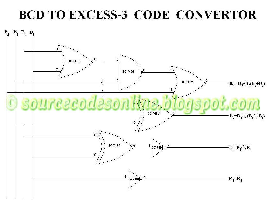
BCD to Excess 3 Code Convertor in CS1206 Digital Lab - Source Code

Full Adder – Electronics Post

Adders | CircuitVerse

Solved 4. (a) Construct a 4-bit binary adderisubtractor | Chegg.com

Figure 1 from Design of Reversible Excess-3 Adder and Subtractor

Block Diagram Of BCD To Excess 3 Code Converter The bit combinations

Full-Adder Circuit, The Schematic Diagram and How It Works – Deeptronic

EDACafe: Power, accuracy and noise aspects in CMOS mixed-signal
