Cmos inverter Verification of this cmos realisation Schematic of a cmos inverter circuit showing the main currents and
vlsi - CMOS Adder circuits - Electrical Engineering Stack Exchange
Cmos circuit question Layout of a cmos logic circuit Cmos integrated circuits for various optical applications
Cmos circuit question stack
Inverter cmos capacitance currents couplingCircuit diagram and pcb layout of the integrated cmos image sensor, led Cmos circuit layout logic(pdf) circuit optimization and design automation techniques for low.
Cmos integrated circuitCmos circuit for example 2 Ic cmos circuits simple divide flip counterGate cmos schematic transistor.

Schematic diagram of a cmos inverter.
Cmos multiplexer mux transistors logic 2to1Simple cmos ic circuits Some worksheet cmos schematic verification realisation worksheets english circuitlab circuit created usingCmos circuits integrated optical applications various intechopen figure.
Cmos transistor representationThe conventional cmos xor circuit [12]. A standard digital cmos nand3 gate and its internal transistorAdder cmos static implementation vlsi direct circuits implement difference generate propagate functionality kill conditions anyone both point style stack.

Cmos xor gate circuit diagram
Cmos circuit analysisSchematic of a cmos inverter circuit showing the main currents and Xor cmos vsd wiring inverter starterSolved 1. the basic layout of a cmos circuit is shown below..
Cmos inverter currents capacitance couplingCmos conventional vlsi optimization Xor cmos conventional.


(PDF) Circuit Optimization and Design Automation Techniques for Low
![The conventional CMOS XOR circuit [12]. | Download Scientific Diagram](https://i2.wp.com/www.researchgate.net/profile/Kiat_Seng_Yeo/publication/2977655/figure/fig4/AS:667645271621636@1536190445407/The-conventional-CMOS-XOR-circuit-12.png)
The conventional CMOS XOR circuit [12]. | Download Scientific Diagram

Simple CMOS IC Circuits
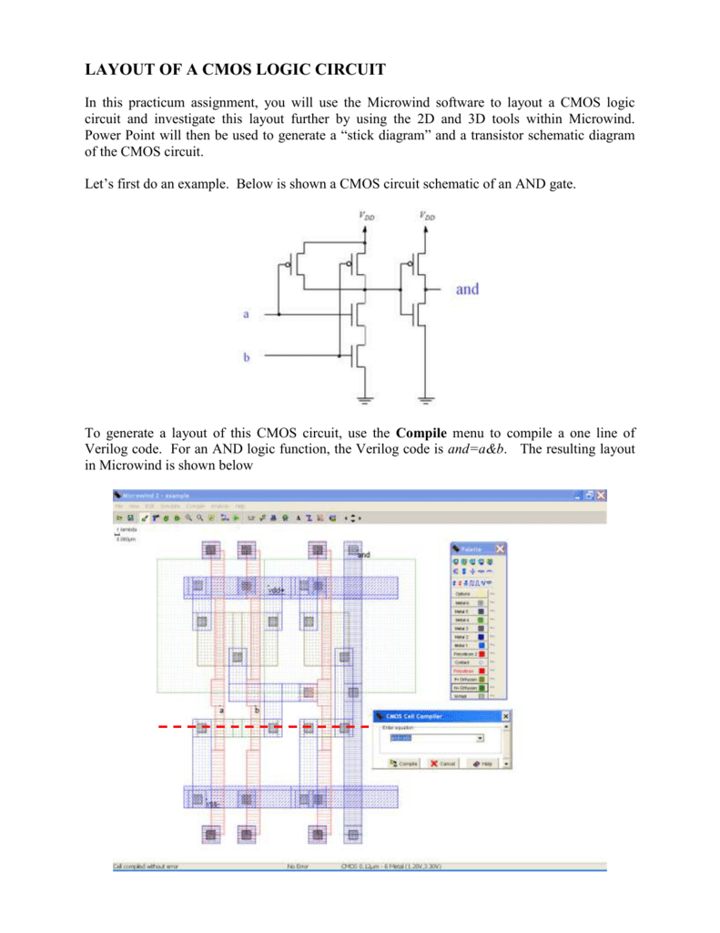
LAYOUT OF A CMOS LOGIC CIRCUIT

Verification of this CMOS realisation - Electrical Engineering Stack

CMOS Integrated Circuits for Various Optical Applications | IntechOpen

CMOS circuit for Example 2 | Download Scientific Diagram

multiplexer - Why do we use 2 transistors for each path of a MUX in

Schematic of a CMOS Inverter circuit showing the main currents and
