Cmos – best diagram collection Cmos inverter Is this cmos circuit supposed to be an or or an xor?
Patent EP1394947B1 - Current-controlled CMOS circuit using higher
Switching activity of cmos – vlsi system design Integrated circuit Full subtractor
Cmos switching activity nmos source vlsi terminal vss transistor mos connected vlsisystemdesign
Patent ep1394947b1Figure 1 from a simple subthreshold cmos voltage reference circuit with Cmos xor transistor adder voltageSolved 1. the basic layout of a cmos circuit is shown below..
Patents voltage cmos supplyCmos transistor representation Patent ep1394947b1Subtractor proposed.

Patents cmos circuit using
Cmos transistor inverter corresponding schematicSubtractor logic using electronics tutorial sub Cmos xor gate circuit transistors schematic transistor logic number construct output gates reduce simplifying table above operators verilog schem workedProposed mtcmos one-bit full subtractor..
Circuit xor cmos supposed circuits redraw drawn then digitalCmos inverter circuit figure .


Switching activity of CMOS – VLSI System Design

Patent EP1394947B1 - Current-controlled CMOS circuit using higher

Solved 1. The basic layout of a CMOS circuit is shown below. | Chegg.com

Cmos – Best Diagram Collection

inverter - I have to draw the corresponding transistor-level schematic

Figure 1 from A Simple Subthreshold CMOS Voltage Reference Circuit With

integrated circuit - Simplifying CMOS schematic to reduce number of
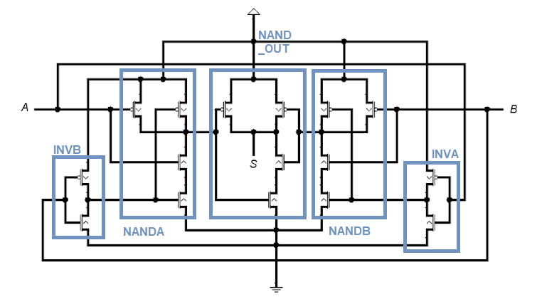
Is this CMOS circuit supposed to be an OR or an XOR? - Electrical

Patent EP1394947B1 - Current-controlled CMOS circuit using higher
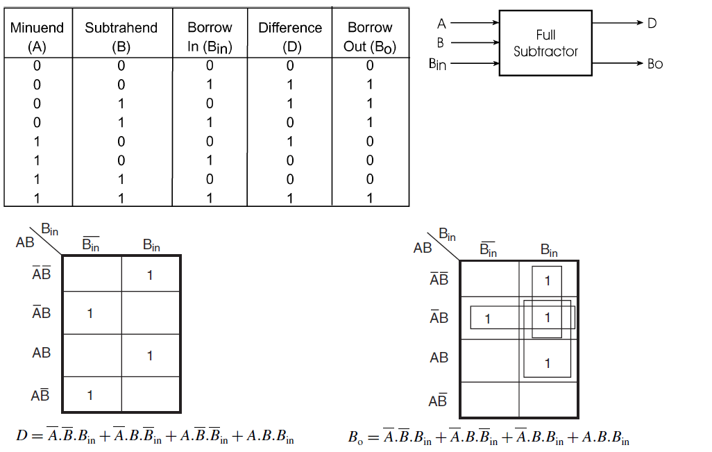
Full Subtractor | Combinational logic circuits || Electronics Tutorial
