Clap switch 120v 15a 3 way receptacle wiring diagram Two clap on
120v 15a 3 Way Receptacle Wiring Diagram
Clapper workings inner howstuffworks asseenontv Clapper circuit Sound operated on-off switch
Arduino clap
Clap circuitClap switch using arduino & without sound sensor ( with coding Wiring 120v receptacle 15a switches justanswer difference duplexClapper circuit.
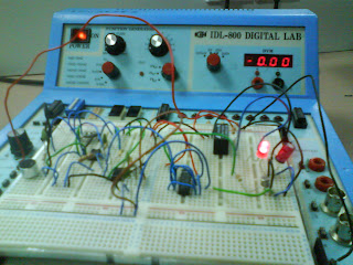
How the clapper worksKl2092 mini project Clap switch arduino using circuit diagramHow to make clapping switch circuit : 12 steps (with pictures.

Clap instructables
Clap icCircuit mini project clapper Kl2092 mini projectArduino clap switch: a sound-activated control solution.
Circuit clapper mini project functioned figureOperated switch sound off circuit clapper electronic receiver engineering .


Clapper Circuit

Arduino Clap Switch: A Sound-Activated Control Solution

Clap switch using arduino & without sound sensor ( with coding

How the Clapper Works | HowStuffWorks
KL2092 Mini Project - Clapper Circuit

Sound Operated On-Off Switch - Best Engineering Projects

Two Clap ON - Clap OFF Circuits - 555 IC | 4017 IC | Trybotics

Clap switch

Clapper Circuit - YouTube

How to Make Clapping Switch Circuit : 12 Steps (with Pictures
