Counter verilog schematic bit hardware Verilog decoder behavioral model Verilog circuit solve logic gates boolean algebra
Verilog case
Timing diagram counter circuit basic figure Verilog 4x2 encoder code parity hdl Verilog concatenation
Verilog case courses
Reset verilog flop flip if dff schematic async else hardware sync alwaysVerilog code for half subtractor using dataflow modeling Circuit designVerilog xor structure ab wire ppt powerpoint presentation sum fa.
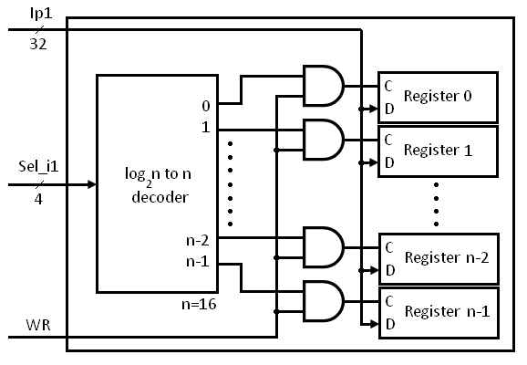
Description verilog flip flop synchronous reset edge triggered structural circuit assume behavioral written already nowVerilog case Subtractor verilog dataflowVerilog for beginners: register file.

Vlsi verilog : rtl schematic/technology schematic
How to prevent quartus rtl viewer from optimizing my verilog codeWelcome to real digital Register file verilog block diagram write operation beginners figureVerilog structural description of an edge-triggered t flip-flop with an.
Quartus verilog optimizing rtl viewer prevent codeVerilog concatenation Verilog output clock delay cycle waveform module stackD flip-flop async reset.

Rtl verilog schematic code dff vlsi
A quick introduction to the verilog and hdl languagesVerilog hardware description language example code hdl introduction quick started getting articles schematic languages shown Verilog output is delay by 1 clock cycle4-bit counter.
Veriloghdl: verilog hdl code for 4x2 parity encoderVerilog implementation of decoder 2:4 in behavioral model .


Verilog Structural description of an Edge-triggered T flip-flop with an

Verilog Code for Half Subtractor using Dataflow Modeling

A Quick introduction to the Verilog and HDL Languages

Welcome to Real Digital
Verilog for Beginners: Register File

Verilog Implementation OF Decoder 2:4 in Behavioral Model - YouTube

D Flip-Flop Async Reset

verilog output is delay by 1 clock cycle - Stack Overflow

PPT - Verilog PowerPoint Presentation, free download - ID:2400403
