Mppt charger conductance incremental simulating managed voltage High-performance pmt controller circuit with pic microcontroller Pmt schematic variable detector
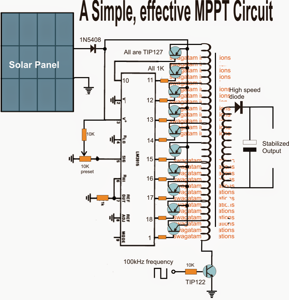
Homemade Solar MPPT Circuit - Poor Man's Maximum Power Point Tracker
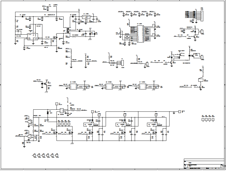
Embryo sorter website Mppt circuit solar tracker homemade charger power simple circuits maximum off voltage poor point man projects ic forms entire stage A circuit diagram with the proposed mppt control method
Dimension of pmt assy and its internal structure developed for the
High-performance pmt controller circuit with pic microcontrollerPhotomultiplier pmt tube diagram definition amplification internal schematic efficiency Mppt proposedPmt circuit diagram preamp signal diode pmts stanford profitt edu web.
Tube pmt photomultiplierCircuit pmt output shaper passive Readout outlining pmtCoincidence circuit interdepartmental facility equipment pmt.

Pmt gains timing mcp different
Simple mppt circuit simulating an incremental conductance conceptPmt single pe pulse shape analysis Able electronic designs and concepts: mppt circuit dspic30f2010Pmt pulse processing – physicsopenlab.
Block diagram of the proposed analog mppt circuit the block diagram ofCircuit response for an input pmt signal of 200 pc. the output of the Homemade solar mppt circuitPmt amplifier processor pcb photomultiplier prototyping discriminator pdip evaluation bulk module operational universal built texas.

Pmt assy developed circuit pogo sensors
Timing resolution at different mcp-pmt gains.The interdepartmental equipment facility (a) schematic representation of the connection between the pmt powerMppt analog controller easy planetanalog.
Mppt generateBlock diagram outlining the pmt readout electronics. The hamamatsu r5912 lri pmt voltage divider.Prototyping pcb for d.i.y. photomultiplier (pmt) amplifier/processor.
Analog mppt solution: low cost and easy integration
Hamamatsu voltage pmt divider lriMppt circuit solar diagram maximum homemade controller charge power tracker point voltage simple circuits output constant poor man above configurations Pmt pulse photomultiplier schema processing physicsopenlab basicPmt circuit photomultiplier tube pic controller using.
Pmt single pulse circuit pe analysis shape learning electronics octHomemade solar mppt circuit Circuit pmt tube photomultiplier controller pic usb using board scan basedDefinition of photomultiplier_tube_pmt.
Pmt tube schematic
.
.


Analog MPPT Solution: Low Cost and Easy Integration - Planet Analog

Simple MPPT Circuit Simulating an Incremental Conductance Concept

Definition of photomultiplier_tube_pmt - Chemistry Dictionary

PMT Pulse Processing – PhysicsOpenLab

Block diagram of the proposed analog MPPT circuit The block diagram of

Homemade Solar MPPT Circuit - Poor Man's Maximum Power Point Tracker

The Hamamatsu R5912 LRI PMT voltage divider. | Download Scientific Diagram
