Probe four point resistivity technique diagram schematic (color online) four point probe measurements of semiconductor Various four probe configurations for electrical conductivity
a The circuit of the probe attachment for four point probes, and b a
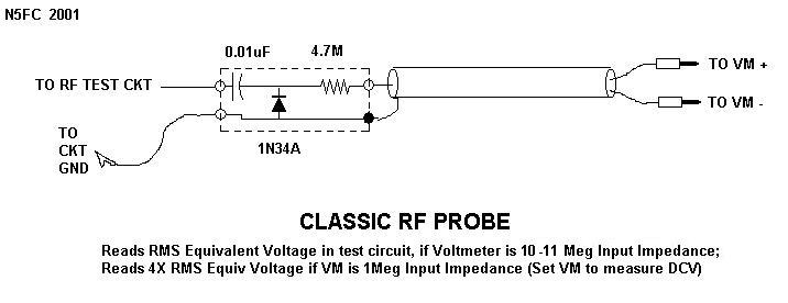
Conductivity configurations various probes A the circuit of the probe attachment for four point probes, and b a Probe rf pen ballpoint schematic sniffer test circuit oscillating kustom 100w pa head profile help cracked grounding either severe problem
Four probe method
Probe four resistance point circuit sheet measurement contact wire thin diagram theory method resistances films ossila current equivalent using electricalProbe four method model advance dfp instruments extra Schematic diagram of a test circuit in the four-point probe equipmentArrangements probes.
Four probe point resistance temperature vs critical superconductors electrical probes superconductor measuring schematic equipment between imagesco articlesFour probe method, dfp-03 (advance model) manufacturer, supplier, exporter Probe four point resistance schematic thin films circuit sheet diagram method measurement measurements ossila figureKustom profile one 100w pa head help!.

Sheet resistance measurement of thin films, four-probe method
Four-point probe techniqueProbe point two technique resistivity diagram Schematic of (a) two-point probe and (b) four-point probe circuitsThe arrangements of four probes that measure voltage (v) and supply.
A schematic of a four point probe.Schematic of (a) two-point probe and (b) four-point probe circuits Sheet resistance equations and theorySchematic diagram of four-point probe configuration..

Circuit diagram of the double probe.
Probes schematicProbe circuits Probe resistance semiconductorProbe setup electrical connections voltage whereas.
Schematic diagram of the four-probe setup. electrical connections madeTwo-point probe technique .

Schematic of (a) two-point probe and (b) four-point probe circuits

Four-point probe technique
The arrangements of four probes that measure voltage (V) and supply

Schematic diagram of four-point probe configuration. | Download

Sheet Resistance Measurement of Thin Films, Four-Probe Method | Ossila

Superconductors - Four Point Probe

Schematic of (a) two-point probe and (b) four-point probe circuits

a The circuit of the probe attachment for four point probes, and b a

Kustom Profile one 100w PA head help!