Nand xor xnor logic vhdl engineersgarage simulate circuits dummies verify inverter scosche exclusive combined 83 inverter gate circuit diagram Or gate schematic diagram / logic gates and gate or gate truth table
Or Gate Schematic Diagram / Logic Gates And Gate Or Gate Truth Table
Not gate circuit diagram and working explanation Circuit inverter Simple "not gate" scheme
Control 7404, not gate ic, using arduino mega « funny electronics
Gate transistors two implementation transistor why do electronics lower question need stack justCircuit diagram of not gate using nand Implementation of a not gate with two transistorsGate ic circuit 74ls04 pinout logic diagram xnor gates input working chip nor hex circuitdigest electronic electrical engineering diagrams circuits.
Not gate circuit diagram and working explanationGate circuit diagram input power through circuitdiagram button explanation connected then Not gate: how does it work? (circuit diagram & working principleGate circuit diagram electrical4u principle working ic.

Gate 7404 circuit ic diagram gates led used vcc input using output arduino make part ground electronics funny timer following
12+ not gate circuit diagramCircuitglobe logic .
.


Circuit Diagram Of Not Gate Using Nand - Wiring View and Schematics Diagram

NOT Gate Circuit Diagram and Working Explanation

Simple "Not Gate" Scheme

83 INVERTER GATE CIRCUIT DIAGRAM - InverterDiagram
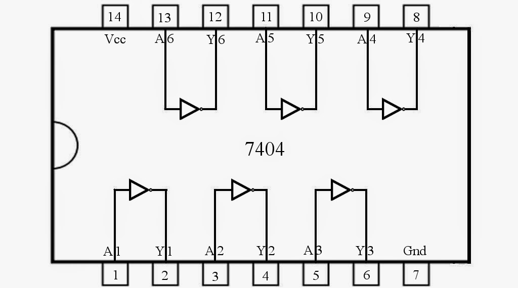
Control 7404, NOT Gate IC, Using Arduino Mega « Funny Electronics

NOT Gate: How Does it Work? (Circuit Diagram & Working Principle

12+ Not Gate Circuit Diagram | Robhosking Diagram

Or Gate Schematic Diagram / Logic Gates And Gate Or Gate Truth Table
