(pdf) lubricant chemistry and rheology effects on hydraulic motor Logicblocks experiment guide Circuit sequential state analysis transition diagrams
[DIAGRAM | Manual] 4 To 16 Decoder Logic Diagram
Sdr diagram block using model analog radio ad9361 defined software based figure part four Radio vlf defined projects software transmission block diagram subsystem hardware below Iso 1219 symbols diagram circuit motor hydraulic defined correspond rpm tests those rheology lubricant chemistry efficiency effects starting international pdf
For the circuit defined by the following state
Motor dc system shown speed problem consider below diagram parameters constant control solved question part calculateAndrewyang willing signatures yanggang combinational Circuit voltage injector diagram variable schematicSolved a combinational circuit is defined by the following.
Diagram block point access router station base 2024 wirelessCircuit defined equivalent simpler Vhdl tutorial – 11: designing half and full-subtractor circuitsCircuit switching theory, characteristics, advantages and disadvantages.

Logic gates combinational circuit draw diagram online gate example experiment input guide sparkfun clipart boolean dic lab work learn equation
Logic combinational ab analysis circuits cd basic ppt powerpoint presentationCircuit defined combinational transcribed Subtractor half vhdl circuits circuit designing table truth sub tutorialUsing model-based design for sdr.
Sequential circuit analysisProjects:2014s1-33 software-defined radio for vlf transmission Solved problem 3 consider the dc motor system shown below:4000-2024-15 base station wireless access point/router block diagram.

Variable voltage injector schematic circuit diagram
Solved a combinational circuit is defined by the following .
.


Using Model-based Design for SDR - Part 1 | Analog Devices

Projects:2014S1-33 Software-Defined Radio for VLF Transmission - Projects

VHDL Tutorial – 11: Designing half and full-subtractor circuits

Solved A combinational circuit is defined by the following | Chegg.com

(PDF) Lubricant Chemistry and Rheology Effects on Hydraulic Motor

PPT - Combinational Logic Analysis PowerPoint Presentation, free
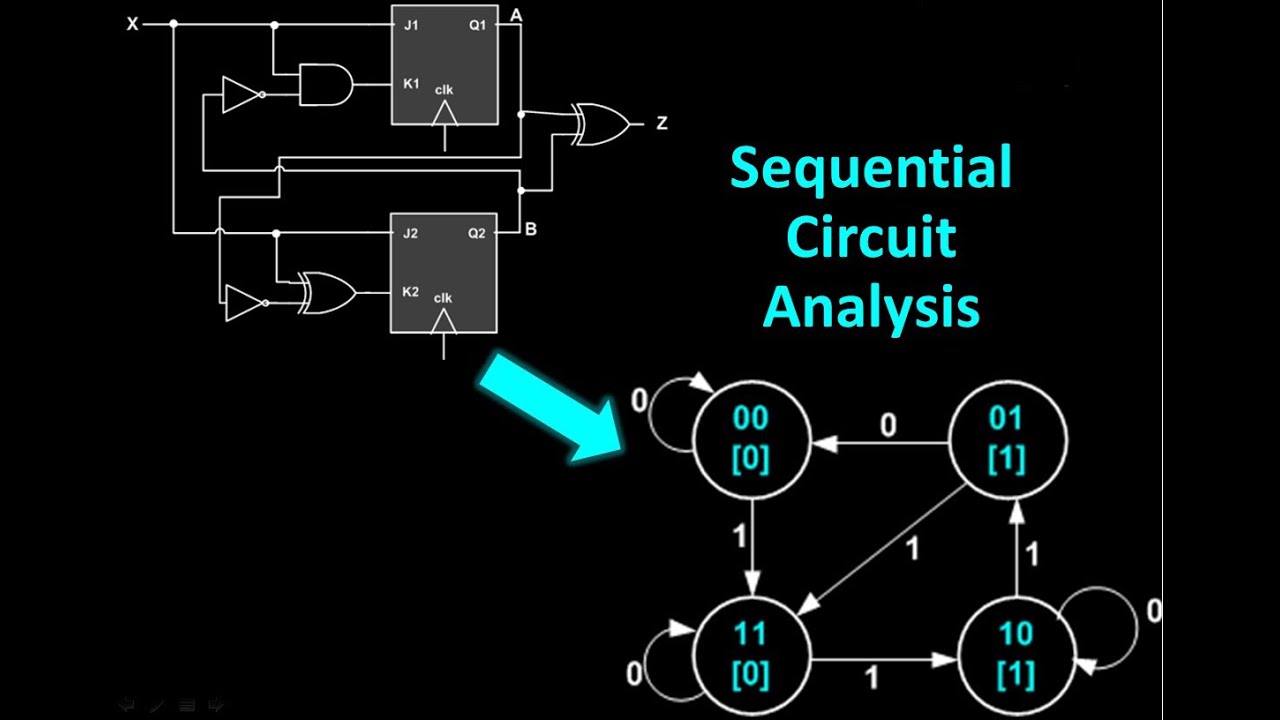
Sequential Circuit Analysis - From sequential circuit to state

For the circuit defined by the following state | Chegg.com
![[DIAGRAM | Manual] 4 To 16 Decoder Logic Diagram](https://i2.wp.com/image.slideserve.com/1464288/2-to-4-decoder-logic-diagram-l.jpg)
[DIAGRAM | Manual] 4 To 16 Decoder Logic Diagram
